Notes and Procedures
Lighting Systems designed and developed by PMMI Lighting LLC operate through accessing a Configuration File. This file is located on a USB flash drive, which is plugged into the Raspberry Pi computer located on the PMMI Lighting HUB. The configuration file contains a sequence of commands written in a language specific to PMMI Lighting’s System. It provides software instructions to the PMMI Lighting Controller. A Microsoft Excel spreadsheet is provided to complete this process.
If you are ready to customize your system, take the USB flash drive out of your system and copy the excel spreadsheet onto your computer. The file to copy will be the file that ends in .xlsm. While you are working on the customization, plug the USB flash drive back into your system so it will continue to work as you are modifying the spreadsheet. Anytime you plug the flash drive into the system, please reboot the system. To do this, power it down and back up again.
Before changing your excel spreadsheet do a save as, and rename the new file, adding a version number at the end. This will allow you to retain the original, in case you need to reference it later.
The process to create a new configuration file to run your system will be covered on page 14 of this manual.
The Excel spreadsheet is comprised of multiple tabs (sheets) used to define various aspects of the installation. When filling information in the excel spreadsheet, NEVER copy and paste as that can corrupt the file. Note also that fields in the spreadsheet to be populated manually are highlighted in light grey. Other fields that are automatically populated will receive an error if entry is attempted. Tabbed sheets are:
- General Tab– name and location of the installation. There is also a macro button on this sheet used to create the configuration file once all tabbed sheets are filled out.
- Channels Tab– identification of each physical Channel in the installation using information pulled directly from the Cabling Plan. It also supports the specification of a maximum intensity for each channel.
- Areas Tab– identification of named Areas as collections of Channels. For example, a switch can access and control one or more Areas.
- Scenes Tab– identification of named Scenes as collections of Areas, where each Area can be illuminated at a different illumination level from 0 to 100%. Scenes represent the secondary identification of things that are controlled by the controller. For example, a switch can be used to trigger a Scene.
- Switches Tab– like channels, information on the Switches tab is pulled directly from the Cabling Plan. It serves to instruct the controller about how switches are connected through switch daisy chains and what they should control and how they should control it. (e.g. toggle, dimmer, etc.).
- Events Tab– identification of named Events that will automatically execute at specific times.
- Triggers Tab– like Channels and Switches, information on the Triggers tab is pulled directly from the Cabling plan. It serves to instruct the controller about motion detectors, which cables theyare attached to, and what action to take when a trigger is detected.
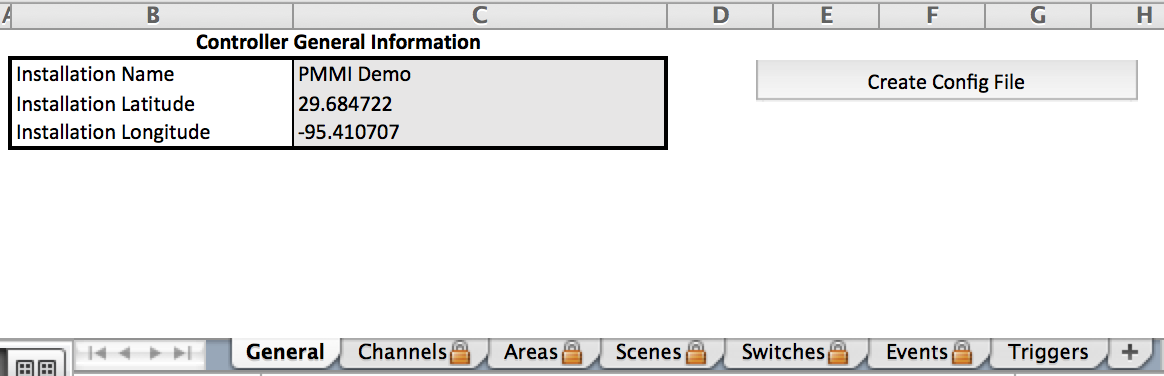
General Tab
Controller General Information
This General Information is setup at the factory. Included for information purposes only.
- Installation name and location are specified here (only 40 characters can be used).
- The latitude and longitude should closely represent the lat/long coordinates of the installation.
- These are used to calculate the time of sunrise and sunset, which can be used in timed Events.
- Latitude is a number from 90.0 to negative 90.0, where positive numbers represent latitudes north of the equator.
- Longitude is from 180.0 to negative 180.0 where positive numbers are east of the zero meridian and negative numbers are west.
Create Config File Button
- This is used to automatically create the configuration file from spreadsheet contents,
- Will be addressed later as this is used after all the tabs are filled out.
Channel Tab
This is a list of each physical Channel in the installation. This information serves to instruct the controller on the physical channel layout.
The Channel Numbers in the left column represent the physical Channel Numbers labeled on Channel fixture cables that home run to the Control Panel.
The Max Level field allows a maximum intensity for that Channel from 0 to 100% to be set. The default is 100% if nothing is input. It is recommended that the default be used for initial configuration. If a space is too bright, this can be changed to reduce the max light level for that space.
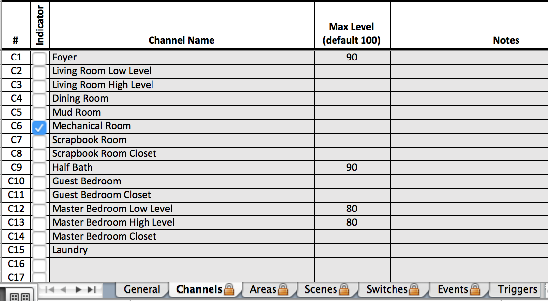
Notice the Mechanical Room has a check in the Indicator column, this can be checked to be any room or number of rooms. The channel indicated will blink:
- One time when the system is ready after a reboot
- Three times when vacation mode is turned on
- Twice when vacation mode is turned off
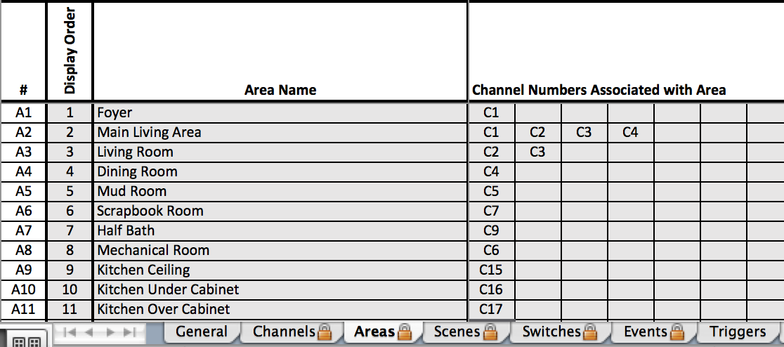
Areas Tab
Using Channel numbers identified on the Channels Tab, create Area names to identify physical spaces in the facility where such spaces may be controlled as a group. When entering Channel numbers, only enter the integer value (1, 2, 3, etc.) as the “C” designation is automatically added by Excel.
Each named Area can contain as few as one Channel, and as many as all defined Channels.
Scenes Tab
This sheet identifies Scenes using the Area numbers. Each Area is given an illumination level. Scenes can be triggered with either a switch or through a timed event.

Switches Tab
The Switches tab is used to instruct the controller on which switches are physically attached to switch daisy chains. The Control Type is used to specify the behavior of a switch. A pull-down menu is available in Control Type.
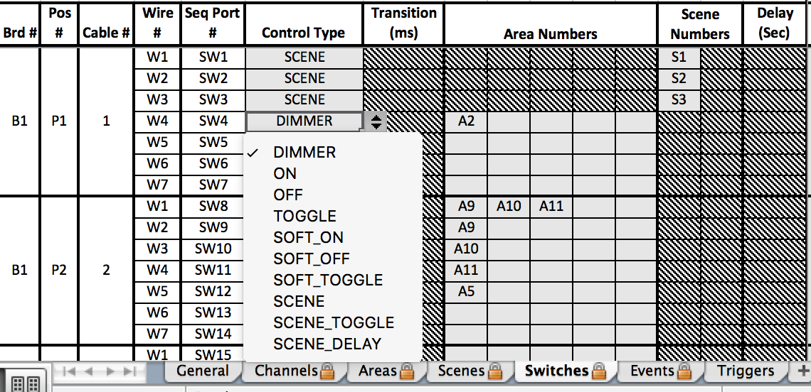
- DIMMER– Switch behaves like a momentary on/off toggle and as a dimmer. If the button is pressed and released quickly, Areas specified toggle on or off. If the button is pressed and held, Areas will either dim up or down depending on the initial state. If lights were off, they will ramp up. If lights were on, they will dim down. The dimming rate is set so that the full range (0 to 100%) is achieved in five seconds.
- ON– Switch instantly toggles fixtures in the specified Areas ON.
- OFF– Switch instantly toggles fixtures in the specified Areas OFF.
- SOFT_ON– Switch toggles fixtures in the specified Areas ON, ramping to full illumination over 1/2 second, this is default. Transition times up to 5 seconds can be specified.
- SOFT_OFF– Switch toggles fixtures in the specified Areas OFF, dimming to 0% illumination over 1/2 second. Transition times up to 5 seconds can be specified.
- SOFT_TOGGLE– Switch toggles fixtures in the specified Areas ON or OFF depending on present state, ramping to full or zero illumination over 1/2 second.
- SCENE– Switch triggers one or more Scenes rather than Areas. Scenes are defined on the Scenes Tab. If Scene is selected for Control Type, columns under Area Numbers are hidden, and columns under Scene Numbers are shown available.
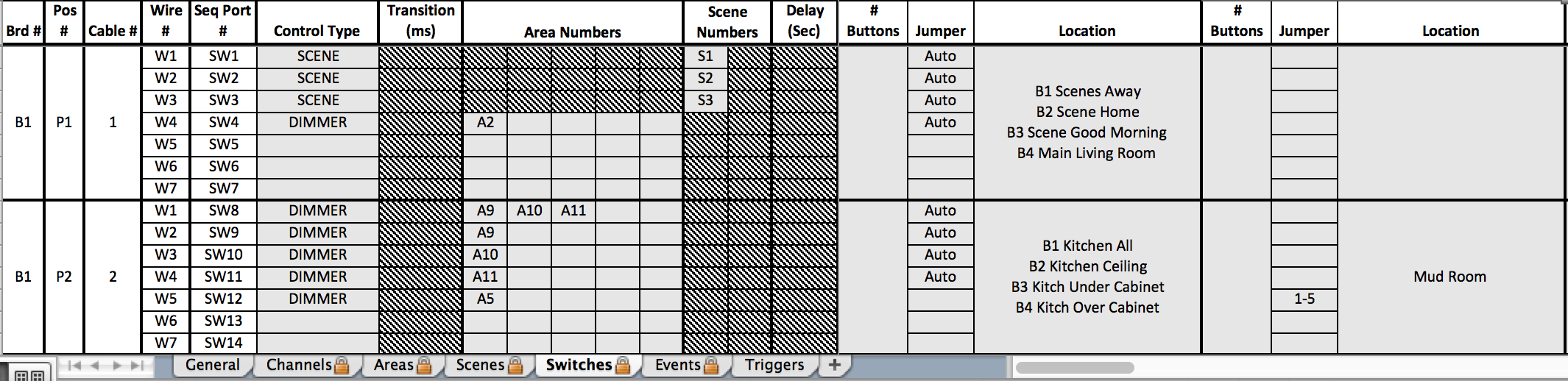
For all Control Types except Scene, one or more Areas can be associated with the switch. If Control Type is Scene, one or more Scenes can be set to trigger when the switch is pressed.
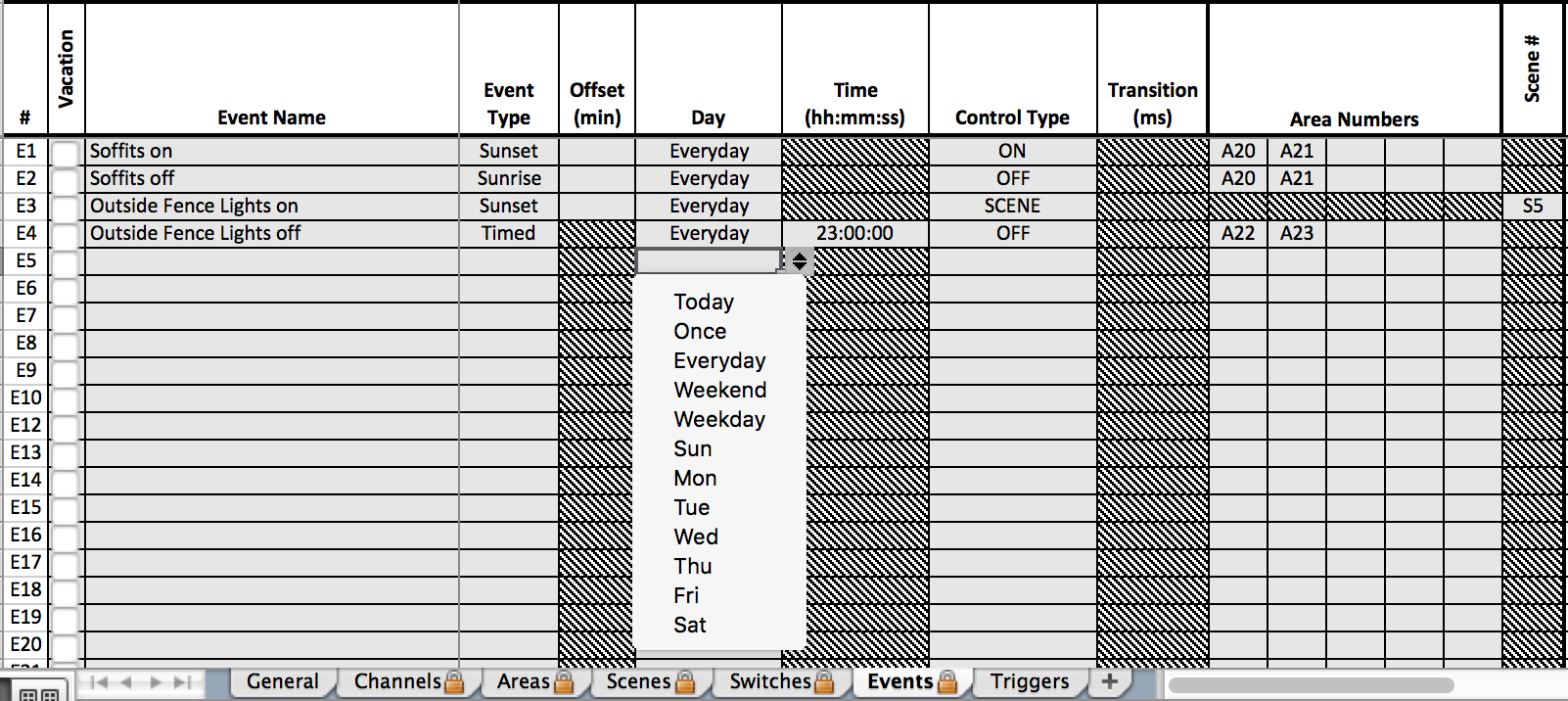
Events Tab
The Events tab is used to setup actions that occur automatically and at specific times and intervals. Event times can be a specific time of day based on a 24 hour clock 00:00:00 (midnight) to 23:59:59, or can be tied to sunrise or sunset. Like a switch, an event can control one or more Areas, or can trigger one or more Scenes.
For Event Type, Day, and Control Type, pull-down menus present options. Options for Event Type are “Sunrise”, “Sunset”, and “Timed”. If Sunrise or Sunset are chosen, an optional “Offset” can be selected. In the example below, “Soffit On” will trigger at sunset everyday.
Using options under “Day”, the event can be set to trigger “Today”, “Once”, or at recurring intervals “Everyday”, “Weekdays”, “Weekend”, or a specific day of the week. Most popular settings are “Everyday”, “Weekday” and “Weekend”.
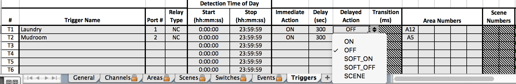
Triggers Tab
The Triggers tab is used to instruct the controller about which motion detectors are physically attached to motion ports on Motion Reader boards.
At this time, the motion detectors that are shipping from PMMI Lighting, LLC are Relay Type NC (normally closed).
When motion is detected, two events are scheduled to occur — one immediately and another some number of seconds in future. “Delay” specifies the number of seconds (from 0 to ∞) between the immediate action and the delayed action. Typically, the immediate action is to turn lights in an Area ON and the delayed action is to turn them OFF. Transition time can be set for “SOFT” actions (default transition time is 1/2 second).
If during the interval between the immediate and delayed actions motion is detected again, the delayed-action time is reset. The delayed action will only occur after motion has ceased.
The following example turns Laundry and Mudroom lights on immediately, and then turns them off five minutes (300 seconds) after motion has stopped.
Configuration File – Creation and Installation
Once information in the tabbed sheets discussed previously are populated, the Configuration File can be created.
On a PC running Windows 7 or later,
- Go to the “General” tab on the configuration spreadsheet.
- Click on the button labeled “Create Config File”.
- This will automatically create the configuration file used by the PMMI Lighting Controller to run the system.
- Select to save this new file.
- Save it in the same place you have stored your exel spreadsheet while working on your new configurations.
- Click OK and the new configuration file will be saved on your hard drive.
- Power down your lighting system.
- Remove the flash drive from your PMMI Lighting HUB located in the Lighting Control Panel.
- Plug the USB drive into the PC that has the excel spread sheet and .txt file on it.
- Note the drive (e.g. H:\) is assigned to the USB drive.
- Copy the excel spreadsheet and the new config file “pmmi_cfg.txt” to the USB drive.
- It will ask you if you want to write over the “pmmi_cfg.txt” file on the USB drive.
- Say Yes, as this is the file that the system reads to run your system. You can only have one on the USB drive at a time.
- Remove the USB drive from the PC, plug it back into the PMMI Lighting HUB.
- Power up the PMMI Lighting System.
- The system will take up to a minute to boot and then the new configuration is loaded.
- The area that has been specified with the “Indicator” check mark with flash once when the system is booted and ready.
The Customer Service Department at PMMI Lighting, LLC is available via email, Skype or phone to answer any questions you might have.
Please call or email to set up an appointment for one-on-one training to customize your system.