Important installation notes before getting started.
No Ox should be applied to all cable ends. See video below for instructions. One jar included with each system.
Applying NO OX to RJ45 Connectors
Zip Tape Labels
All home run cables,cables terminating in the control panel, should be labeled on each end designating either the cable# or the location identifier.
PMMI Lighting does not sell this item, but it is readily available online. Below is a link to the label maker in the video. You may find other systems or suppliers, the most important thing is that ALL cables are labeled. (link to label maker)
Platinum Tools EZ RJ45 Demonstration

Click for Video / While this isn’t a video we created, it’s a good one to show the tool and connector we recommend to create your Cat5 Cables needed for our system. The strain relief is NOT needed for our system, so save some money and just purchase the Cat5E connector. Tools NOT included with system. PMMI Lighting does not sell these items, but they are readily available online and at building supply retail outlets.
Cables, Connectors and Tools
Go to Pricing, Cabling and Power for information on the proper cable, connectors and tools needed for the installation. Installer is responsible for the purchase of these materials. PMMI Lighting LLC does not provide the cables, connectors or tools.
INSTALLATION
Cat5 Cabling
Make Cat5, Cat5e or Cat6 cable runs in accordance with the Cabling Plan developed in the Planning stage. All home run cables,cables terminating in the control panel, should be labeled on each end designating either the cable# or the location identifier.
Recommended Cat5, Cat5e or Cat6 cable color usage:
- Red – Channels for PMMI LED fixture chains
- Green – wall switch chains
- Yellow – motion detectors
Using color-coded cable is important to distinguish between the different type cables, and also to distinguish between Cat5, Cat5e or Cat6 cable used for the PMMI Lighting System and cables used for computer networks. Plugging PMMI Lighting cables, and especially red fixture cables, into network ports on laptops, routers, or other computing hardware can damage that equipment and/or PMMI Lighting components.
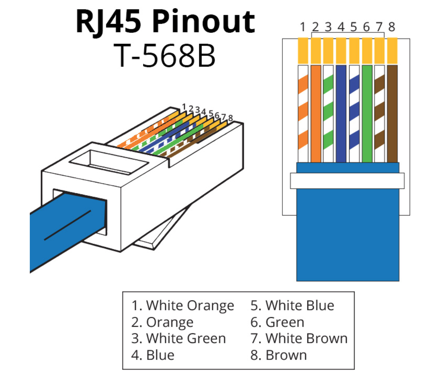
All cables should be terminated using RJ45 male connectors using the T568B termination standard as shown. (PDF file available here of Cat5, Cat5e or Cat6 Cabling info.) Be sure to leave excess cable at both ends —minimum of 4′ extra at the control panel and 2′ extra at the component ends.
Label all cables terminating at the Control Center. It is strongly recommended that a label be attached to each cable identifying it.
PMMI Lighting supports Ethernet for Internet for security purposes. A Cat5, Cat5e or Cat6 cable run between the router/firewall to the Control Center is recommended.
Control Center
 The Control Center is typically installed in a utility closet or mechanical room. It’s common but not required to place it near the breaker panel. Position and mount the Control Center at the desired location. The enclosure that holds the Control Center is typically mounted recessed in a 2×4 stud wall, directly to the studs or can by mounted on a plywood wall. Cables for PMMI LED Fixtures and switch daisy chains, along with motion detector cables home run to the Control Center.
Most PMMI Lighting Systems are purchased as package systems including all switches, fixtures, and supporting electronics. All hardware component boards are preconfigured by PMMI Lighting and installed in the enclosure called the Control Center. In the event that component boards are purchased separately, some hardware configuration may be required before installing boards in a Control Center.
Fixture Cables
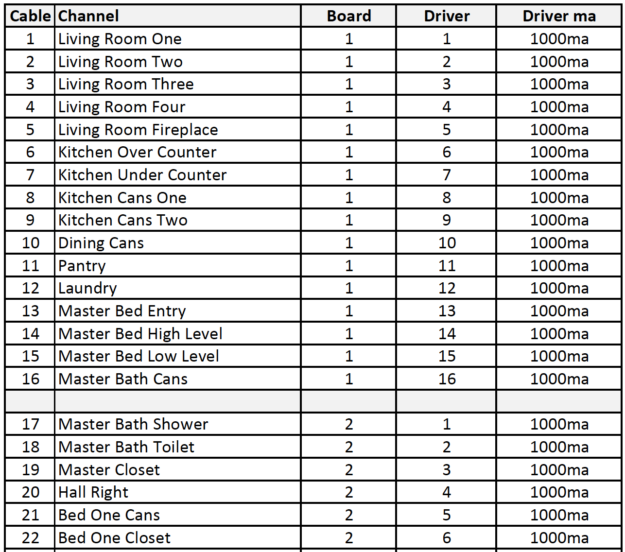
The system has a configuration file that corresponds with the planning document. Plugging cables into proper drivers allows the system to access data correctly from the start of installation.
No Ox should be applied to all cable ends BEFORE plugging into system. See video above for instructions.
Multi Board Systems: Route the red fixture cable labeled “1” into the Control Center and plug the cable into Driver 1 on LED Driver Board 1. (If you have labeled your cable with the channel name, instead of the cable number that’s ok too, just put the correct label in the correct driver input.)
- Plug remaining fixture cables 2 – 16 into ports labeled Driver 2 through Driver 16 on LED Driver board 1
- Plug fixture cables 17 – 32 into ports labeled Driver 1 through Driver 16 on LED Driver board 2
- Continue this process until all fixture cables are terminated at LED Driver boards
Single Board Systems: Simply plug fixture cables 1 – 12 into ports on the Single Board labeled Driver 1 through Driver 12, respectively.
Switch Cables
The system has a configuration file that corresponds with the planning document. Plugging cables into proper inputs allows the system to access data correctly from the start of installation.
No Ox should be applied to all cable ends BEFORE plugging into switches. See video above for instructions.
Multi Board Systems:
- Route the green switch cable labeled “1” into the Control Center and plug the cable into port IN 1 on Switch Reader 1.
- Plug switch cables 2-8 into ports labeled IN 2 through IN 8 on Switch Reader 1
- Plug switch cables 9-16 into ports labeled IN 1 through IN 8 on Switch Reader 2
- Continue until all switch cables are terminated at the Switch Reader board
Single Board Systems:
- Simply plug switch cables 1 and 2 into ports on the Single Board labeled SW 1 and SW 2, respectively.
Motion Detector Cables
The system has a configuration file that corresponds with the planning document. Plugging cables into proper inputs allows the system to access data correctly from the start of installation.
No Ox should be applied to all cable ends BEFORE plugging into motion detectors. See video above for instructions.
Multi Board System: Route the yellow motion detector cable labeled “1” into the Control Center and plug the cable into port IN 1 on Motion Reader 1. Repeat this for all remaining motion detector cables.
- Plug motion detector cables 2 – 8 into ports labeled IN 2 through IN 8 on Motion Reader 1
- Plug motion detector cables 9 – 16 into ports labeled IN 1 through IN 8 on Motion Reader 2
Single Board System: Simply plug motion detector cables 1 and 2 into ports on the Single Board Controller labeled MOT1 and MOT2, respectively.
LED Recessed Down Light
 The standard recessed down light is a light-weight flush-mount fixture that can be installed directly into sheet rock, artificial ceiling, or other ceiling material with no physical mounting to the ceiling joist. And because these fixtures operate at low voltage and low temperature (100°F), use of a “fixture can” behind the ceiling material is optional. Cans are available from PMMI Lighting, and are recommended if insulation is used around fixtures.
To install fixtures without cans:
- Locate and mark fixture location on the ceiling or mounting surface being careful to locate fixtures clear of ceiling joists or other obstructions.
- Using a 3 3/4″ hole saw, cut a hole through the ceiling material at the fixture location. Note that a carbide saw will be required for cement-based ceiling material.
- No Ox should be applied to all cable ends BEFORE plugging into fixtures. See video above for instructions.
- Reach through hole and pull red Cat5, Cat5e or Cat6 cable(s) down through the hole. Plug the red Cat5, Cat5e or Cat6 cable coming from the Control Center into the “IN” of the first fixture in a Channel Cable run. Then plug the jumper cable into the “OUT” of the first fixture into the “IN” of the second fixture. If fixture is located in the middle of a Cat5, Cat5e or Cat6 daisy chain (see Cabling Plan), attach one cable to the connector labeled “IN” and the other to the connector labeled “OUT”. Continue this until the last fixture in the Channel Cable run. In this fixture, the jumper should plug into the “IN” and the light fixture termination plug should be plugged into the “OUT” jack signaling the end of the run.
- Insert the fixture into the hole and allow the clips to hold firmly in place.
Note that steps 1 and 2 should be complete when raw ceiling material is in place. We recommend ceiling finish (float, texture, paint, etc.) be done before steps 3 and 4 are completed.
 If fixture cans are used, installation should be done before ceiling insulation is installed. This process works best with a helper located above the ceiling to install cans at the same time as fixtures from below. In parallel with the steps 3 and 4 above, the helper should run Cat5, Cat5e or Cat6 cables through the plastic bushing in the side of the can and then pass them down through the hole in the ceiling. Once RJ45 cable connections are made, the helper should hold the can down tight against the ceiling over the hole while fixture and clips are installed from below. The clips will serve to both hold the fixture in place and the can tight against the ceiling from above.
LED Low Profile Recessed Down Light
 The low-profile recessed down light is designed for use where a wiring cavity exists between the base of the cabinet and interior cabinet floor. Low profile fixtures are 3/4″ thick as measured from the back of the face plate. So if 1/4″ material is used for the base, a minimum 1/2″ cavity is required to accommodate the fixture.
The installation procedure is the same for low-profile recessed fixtures as standard recessed fixtures. Use caution however when drilling 3 3/4″ hole through the base to avoid drilling into the floor of the cabinet.
This fixture is also perfect for use in walls, like pantries and closets to allow horizontal lighting where low profile is necessary.
Perfect for above cabinets, this fixture can be placed on top with no installation within the cabinet itself. The flat bottom allows the fixture to lay flat. This allows the homeowner to move around fixtures if desired to feature an above cabinet item.
LED Gimbal Recessed Down Light
 The LED Gimbal recessed down light requires a different hole size than the other recessed down light. The gimbal fixture requires a mounting hole size of 3 1/2″.
The installation procedure is the same for gimbal recessed fixtures as standard recessed fixtures.
Wall Switches
Like PMMI LED Fixtures, wall switches are connected in a daisy-chain manner using Cat5 cable. Each switch chain can accommodate up to seven individual switches. Switches are available in one, two, three, four, or six-button configurations. Each button represents one switch. Buttons are numbered from left to right, top to bottom with the switch oriented with the OPEN SIDE of RJ45 connectors on the back facing down. In other words, put the connectors at the TOP when installing.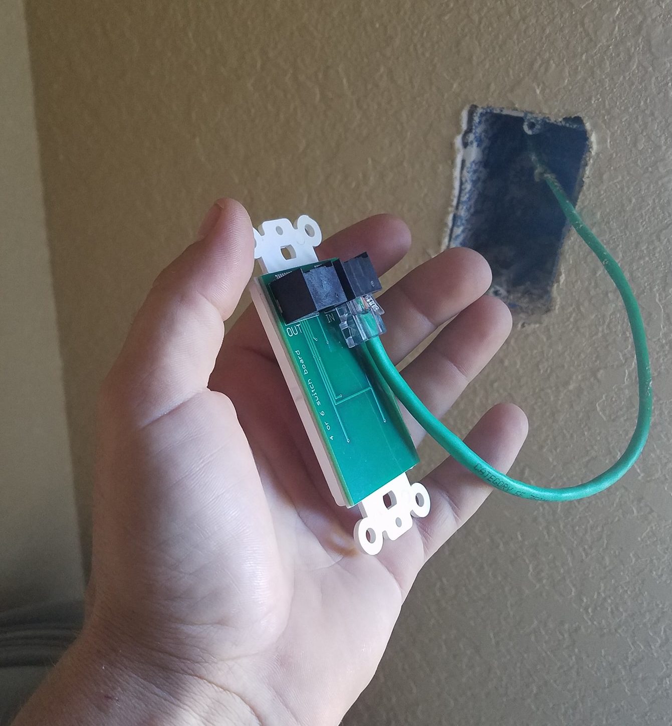
No Ox should be applied to all cable ends BEFORE plugging into switches. See video above for instructions.
- One six-button and one one-button switch
- Or one four-button and three one-button switches
- Or one four-button, one two-button, and one one-button switches
- Or seven one-button switches
Note that it is not necessary to occupy all seven switches on a switch string — any combination up to seven is acceptable.
One, Two, and Three Button Switches — The logical number for each switch is manually set using jumpers on the back of the switch. So for example, to set the top button on a three-button switch to logical switch value one, place a jumper between 1 and 1.
Finally, plug connectors on pre-existing green Cat5 cables at the switch locations into RJ45 connectors on the back of the switch. If the switch in the middle of a switch chain, two cables are present. Plug one of those cables into the RJ45 connector labeled “IN” and the other into the connector labeled “OUT”. It is not important which cable goes to which connector. If the switch at that location is the terminating or final switch on a switch chain, only one cable is present. Plug that jack into either one of the RJ45 connectors on the switch and leave the other connector empty. DO NOT PLUG LIGHT FIXTURE TERMINATION PLUG INTO SWITCH CHAINS.