Lighting Plan
Identifying the fixture layout including fixture types, numbers, and locations is similar to that of a conventional lighting system. One should take into account aesthetics, illumination requirements, and convenience of switch locations. With PMMI Lighting Systems, one also needs to think about planning Channels and defining Areas and Scenes. Click here for more thoughts on lighting intended to produce an attractive and effective, yet economical lighting plan.
Fixtures
A idea that “more fixtures is better than too few” should be adopted in the design process. With PMMI Lighting System’s automation and control capabilities, you can always dim down a space but you can’t turn it up if the space is under lit.
Motion Sensors
Placing motion sensors is straight forward. Determine where you want to detect movement, and identify which Area will be controlled as a result of detected motion.
Switches
With the PMMI Lighting System, more switches are allowed than a conventional system. Where a conventional lighting system might use a single switch to toggle the Living Room, the PMMI Lighting System allows a one to six button switches allowing more creativity. One button might toggle the Living Room, one might toggle the Living Room and Dining Room together, and one a Scene Movie Night, etc.
It is also recommended that more switches is better than not enough. As one gets used to automation opportunities inherent in PMMI Lighting Systems, new Scenes will be defined over time. Having switches available at the right locations will prevent the need for new Cat5 cable runs in the future. With this in mind, add as many switch types and locations you desire throughout the space in the first design stages. PMMI Lighting Systems are about simplicity, so if a one button switch will do the job, don’t install a six button switch as it can get confusing.
PMMI Lighting Concepts That Influence Planning
Channels
A Channel is one or more LED fixtures daisy chained together using Cat5, Cat5e or Cat6 cable. All fixtures on a Channel are controlled together. Whether simply toggling them on or off, dimming, or using special effects, the behavior of any fixture on a Channel is the sames as every other fixture on that Channel.
Examples of channels on a 48V DC system with PMMI Lighting recessed downlights: (remember these are lighting groups to be controlled separately from each other)
- Bedroom Ceiling: 6 lights daisy chained together
- Bedroom Closet: 5 lights daisy chained together
- Bathroom Ceiling: 4 lights daisy chained together
- Bathroom Toilet Closet: 1 light
- Kitchen Ceiling: 2 channels, each with 6 lights daisy chained together
- Kitchen Under Cabinet: 7 lights daisy chained together
Areas
An Area is a Channel or a collection of Channels that are controlled as a unit. Unlike Channels, which are physical associations of fixtures (physically connected with Cat5, Cat5e or Cat6 cable), an Area is a named logical association of Channels in that it is defined in software and can be changed at any time through the configuration file. An Area can contain one or many Channels. A Channel can be assigned to multiple Areas.
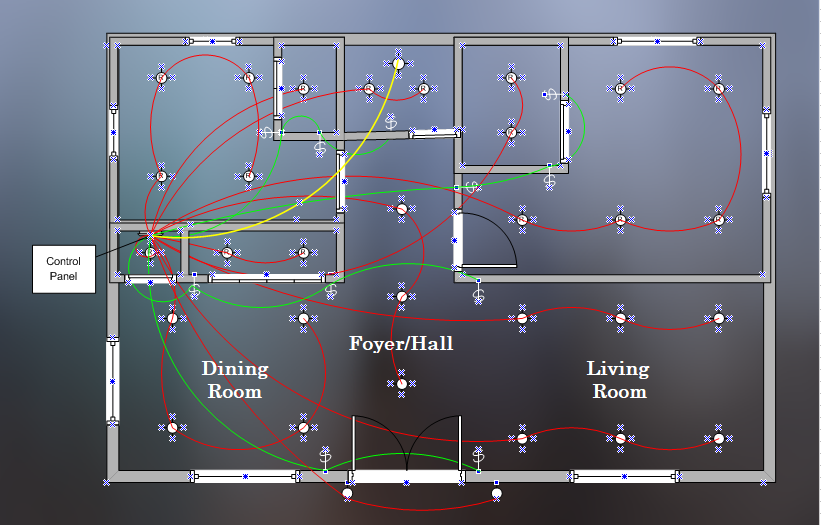
As can be seen in the diagram above for example, the Living Space is comprised of four channels.
- Two Channels of three fixtures each over the living room
- One Channel with four fixtures over the dining room
- One Channel with three fixtures over the entry foyer/hall
It would be useful to create several Areas for this portion of the home. They might look like this.
- Living Room: an area containing the two channels over the living room
- Dining Room: an area with only the Channel over the dining area
- Foyer: an area to contain only the Channel over the entry foyer/hall
- Living Space: an area that contains all four channels so that the entire living space can be controlled with a single wall switch (at bedtime for example)
Wall switches then are be setup to control each of these areas.
Scenes
A Scene is a named collection of Areas that can be taken to a predefined state at the press of a switch. Like Areas, Scenes are logical associations defined in the software configuration file. A Scene can contain up to five Areas and each Area can be set to a unique dimming level.
Using the Areas defined above for example, it might be useful to create a Scene named “Movie Night” that sets the ambiance for watching a movie in the Living Room. It might for example, set the Living Room and Foyer to 5%, and the Dining Room to 25% which would give enough light to highlight snacks on the table. Another popular use of Scenes is to create Scenes called “Good Morning” and “Good Night” that take the entire building to a particular state at bedtime and first thing in the morning.
Control Center
 The Control Center is a centrally located wall-mounted cabinet that houses most of the electronics. It houses the The PMMI Lighting Controller, The PMMI Lighting HUB, LED Driver Boards, Switch and Motion Readers. Cat5, Cat5e or Cat6 cabling for channels, switches, and motion detectors all run to the Control Center.
In a Single Board System, the Control Center houses a Single Board Controller and a PMMI Lighting HUB.
External power must be available at the Control Center location.
- 12V DC, 24V DC, 36V DC, or 48V DC to power LED Drivers
- 12V DC to power other electronics
Internet connectivity is also required. Wifi and cable internet connections are supported. Make sure that either cable Internet or a good WiFi signal is available at the Control Center location.
Cabling Plan
The cabling plan is a direct result of the lighting plan. It is recommended that different colored Cat5, Cat5e or Cat6 cables be used for light fixtures, switches, and motion detectors. As seen in the diagram, we chose red for light fixtures, green for switches, and yellow for motion detectors.
Cabling Layout for Fixtures, Switches, and Motion Detectors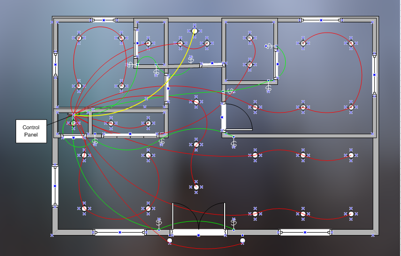
Fixture Cabling
Always label cables. For each Channel (string of fixtures) defined in the Lighting Plan, run one red cable from the LED Driver Board found in the Control Center to the first fixture on that Channel. Then run a red jumper cable from fixture “1” on that Channel to fixture “2”, another jumper cable between “2” and “3”, and so forth for all fixtures on that Channel. Each Channel can have up to 7 fixtures depending on the voltage of the system. The last fixture on a channel is always terminated with a light fixture termination plug.
Switch Cabling
Keeping in mind that up to seven switches can be daisy chained on a Cat5, Cat5e or Cat6 cable, determine cable runs from the Switch Reader Board in the Control Center to all switch locations. The seven switches on the daisy chain cable run, can control up to seven areas or scenes. All the switches on the chain control those SAME seven areas although they can be in different configurations.
Always label cables. For each Cat5, Cat5e or Cat6 switch cable, label and run one green cable from the Control Center to the first switch on the chain. Then run a green jumper cable to switch “1”, to switch “2”, and so on for all switches on the chain. NEVER USE LIGHT FIXTURE TERMINATION PLUGS IN SWITCHES.
Motion Detector Cabling
Suggested placement of Motion Detectors inside a home are closets, pantry, mud room, laundry room, garage, and entry areas. A motion detector controls Areas, turning off and the end of a timed interval if not re-triggered.
Always label cables. To wire motion detectors, label and run a Cat5, Cat5e or Cat6 yellow cable between the location of each motion detector and the Motion Board in the Control Center. Each motion detector requires its own cable.
Forms to help with making a cabling plan can be found here.